By Guy Colpron, P.E., Director of Design
The 2018 revised IEEE 1584 standard has introduced a new, empirically derived, arc flash model to calculate the incident energy of arc flash events. Researchers also developed two additional electrode configurations to accurately calculate the arc flash energy in previously unmodelled configurations.

While the original standard was established in 2002 using data from more than 300 arc flash tests, the new edition is based on over 1,860 additional tests. Researchers concluded the new model produces more accurate results than that of the 2002 model for configurations common in both models. In addition, the new model allows a method to calculate incident energy for other electrode configurations not provided for in the 2002 model. Arc flash testing has validated that the new model has improved the accuracy of the energy calculations. Based on the analysis of the data the IEEE summarizes it conclusions as:
- Based on the relationship between arc energy, incident energy and arc duration; arc duration has a linear effect on the incident energy.
- Distance from the arc, has an inverse exponential affect.
- System X/R ratio, frequency, electrode material and other variables considered, have little or no effect on arc current and incident energy.
- Arc current depends on short-circuit current, bus gap (distance between conductors), electrode configurations, enclosure size and system voltage.
- Incident energy depends on the calculated arc current, arcing duration and working distance. Bus gap is a smaller factor.
The new standard provides a very detailed procedure to calculate the incident energy and the arc-flash boundary. The method uses iterative equations to calculate the arcing current, incident energy and arc-flash boundary providing guidance to achieve the final values. The calculation steps can be summarized as follows:
- Determine the arcing current;
- Determine the arc duration or fault clearing time;
- Determine the incident energy; and
- Determine the arc-flash boundary.
As part of the arcing current calculation process, equipment conductor and enclosure arrangements need to be identified. Most power system equipment contains conductors arranged in similar manner as the test setup electrode configurations presented below. The equipment may also contain more than one electrode configuration depending on the bus and conductor arrangement. The standard does provide some guidance in those cases to select the configuration to use in the arcing current calculation process.
Electrode Configurations
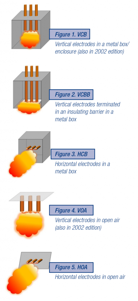
Testing showed that the characteristics of an arc flash event would change based on the orientation of the electrodes. Testing of the vertical orientation as shown in Figure 1 (2002 methodology) yields different results than if the configuration was horizontal (Figures 3 or 5). Determining that electrode orientation influences arc flash energy, further research was performed.
The findings indicated that when electrodes are placed horizontally, the arc plasma is directed outward from the ends of the electrodes. For vertical electrodes, research indicated that electrodes that terminate into an insulator, will direct the plasma cloud toward the enclosure opening after contact with the barrier.
To better accommodate varying configurations (enclosed/open air, vertical/horizontal), the testing program and the subsequent model was updated to include a mix of electrode orientations (Figures 1-5).
Arc Flash Energy Results

(comparison of IEEE 1584-2002 and IEEE 1584-2018)
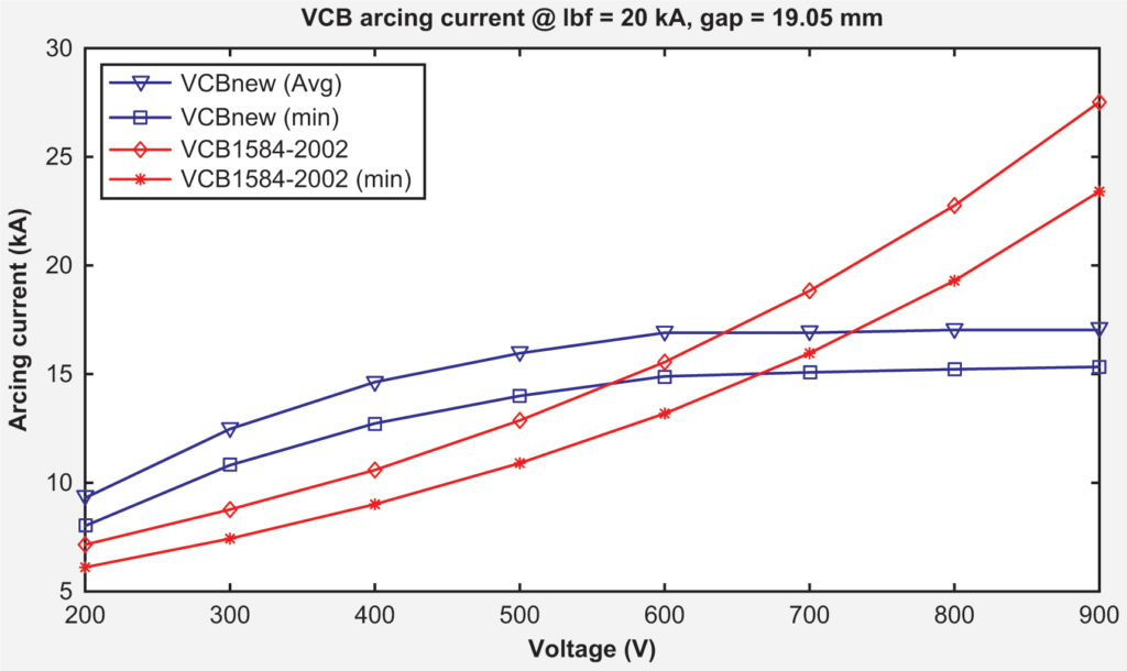
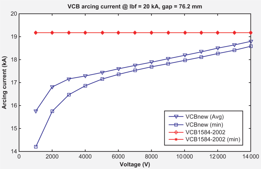
Comparison of the arcing current calculations from the 2002 standard to the 2018 standard provides some very interesting results. The standard is broken into two voltage ranges, 208 V to 600V, and 601V to 15 kV. The following graphs indicate how the new 2018 model performs to the 2002 model.
What Does This Mean for Your Utility?
The new IEEE 1584 standard for calculating arc flash levels will impact all utilities in either identifying an increase of the incident energy or a decrease. Steps should be taken to ensure the Arc Flash incident energy is known allowing utility safety personnel to properly advise management as to the steps to protect their workers. For those responsible for the electrical safety of workers, please consider the following actions:

(comparison of IEEE 1584-2002 and IEEE 1584-2018)
- Update your arc flash study — Per NFPA 70E 130.5 (G), this incident energy should be done every 5 years.
- Ensure your protection devices can clear arcing faults at the highest speed possible to minimize the incident energy exposure. Consider making needed updates during regular maintenance of energized equipment.
- Decrease the exposure to incident energy through remote switching devices.
As with all utility engineering support services, please consider BKI a resource for related questions about the new calculations or if you need to update your arc flash study.

Brown & Kysar, Inc. (BKI) provides hands on, practical engineering, permitting and planning solutions to public power utilities in the West.


